ICs generally have complicated designs, and without a proper pin diagram, you are bound to get lost within the framework. Also, it may so happen that your IC has a number of pins, maybe even more than two hundred. What should you do in such a situation? Finding the function of each pin will be quite complicated. Thus, in such a scenario, you should opt for something that is more robust and is easy to use. If you are also in search of one, you are at the right place.
QFP packages have numerous drawbacks. They generally have narrow pins that are very closely packed. Thus, no matter how well you store them, they get easily damaged. Moreover, if the pins are not welded properly, your IC can easily encounter a short circuit. Also, there might be a high density of pins at some areas of your IC, which might eventually lead to congestion. Thus, in such a scenario, switching to BGA packages is the right solution. Ball Grid Arrays or BGA packages are highly reliable, easy to use and provide robust performance. If you want to know more about BGA PCB, check this out.
However, before understanding how to design a BGA, let us first understand the difference between BGA and PGA.
Contents
BGA vs PGA
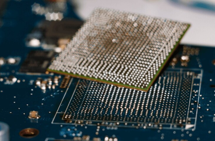
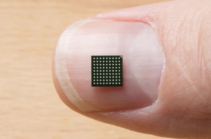
BGA is defined as a chip carrier that is generally used in ICs and makes use of surface mount type of technology. In case you want to mount your microcontrollers and microprocessors, then you should make use of these BGA packages. They will provide you with a large number of interconnected pins, much more than what is offered by the flat ones.
Unlike in the flat packages, the users can utilize the entire surface of the IC in the case of BGA packages. Moreover, they offer higher speed of operation. PGA or traditional pin grid arrays are the predecessor of these BGA packages. The pins in the PGA are arranged in a grid-type fashion and thus covers its surface completely or at times partially. When in operation, the PGA’s pins send signals in between the IC and PCB.
Now, to change the pins in a BGA, you will have to pluck them from the bottom area of the pad. In the beginning, you might need a few small solder balls and place them on the IC either manually or with the help of certain machines.
In general, copper pads are used to connect the BGA integrated circuit with the PCB. The features of these copper pads are much like those of the solder balls. In ICs that are made using advanced technology, these balls are used on both the PCB and the BGA package.
With so many advantages, BGA is here to stay for the long run. Did you ever consider converting your circuit board into a BGA? Well, it is a wise idea to do so because it will not only reduce the size of your product, but it is also much cheaper than buying a new BGA. Hence, before you start designing the BGA, let us understand a few Design Rules.

Source: Seamark ZM
Design Rules
Owing to technological advancements, the BGA packages used for embedded designs have undergone great changes over the last few years. BGAs are generally of two types: micro BGAs and standard BGAs. In today’s world, with the increasing demand for input-output systems, designers are facing numerous challenges. Even experienced designers are at crossroads today. Thus, you need to follow a few design rules before starting with your task,
-
Proper Fanout Strategy:
The main challenge faced by the designers is to create a proper fanout strategy without leading to any fabrication issues or failures. Before starting with the designing part, you need to read through the specifics of the printed board to ensure that you implement the correct strategy. Also, check out the number of pins you need to implement, the layers you need to include and the spacing you need to keep between each pin.

Source: Hackaday
-
Calculate The Number Of Layers Required
Designers are often confused about the number of layers they should include in the BGA. A higher number of layers translates to increased cost of products. However, at the same time, a lower number of layers mean that the amount of noise produced will be higher.
Thus, before starting with the designing process, it is important to calculate the numbers of layers you need to implement in the IC. For that, you need to first calculate the width and spacing between the pins. Also, calculate the number of traces you might need in a single channel. To have a lower number of layers and yet have the IC perform perfectly, you need to reduce the number of input and output pins. Also, it is advised to keep only a few vias. Figure out which vias you need, and then design the rest of the BGA accordingly.
You can also use the”dog-bone” fanout strategy. In this, you need to divide the device into four parts. It will provide easy access to all the other layers, and thus, it will provide an escape route to your IC beyond the device’s edge. The escape process will continue until the fanout process ends.
It is not easy to design a BGA. You need to abide by the rule book at every step to ensure that nothing goes wrong. Before starting, you need to calculate the number of layers you need to prepare, the fanout technique you will follow and the width and spacing of the pins. Planning all this ahead of time will ensure that your design is successful.

Source: YSC Technologies
Final Word
We hope that by now, you know what BGA is and how it differs from PGA. With the advancement in technology, the need for new designs is increasing. As a result, the challenges faced by designers are also increasing at a rapid speed. Make sure to follow the design rules to successfully design your BGA.
