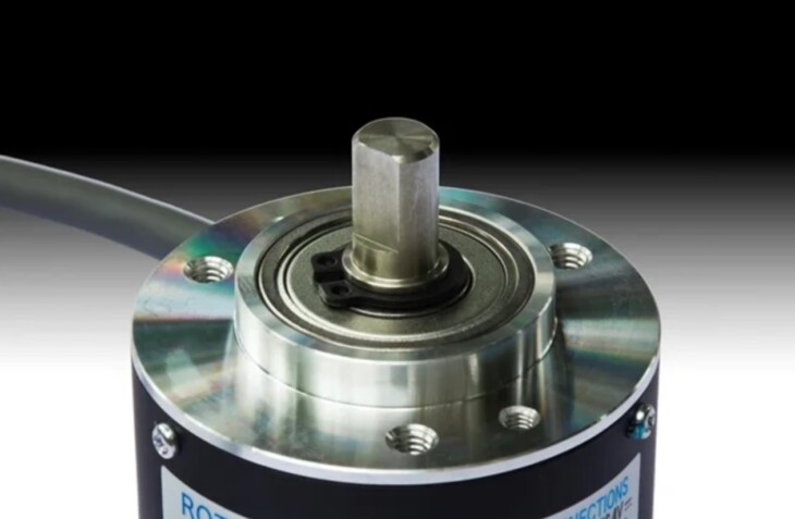
An incredibly crucial and important invention for the world of engineering has been one single complex piece of machinery – encoders, and more specifically, incremental encoders. The purpose of an incremental encoder is that it identifies the shaft’s position or its angular motion which is then converted into either a digital or the more old-fashioned analog code that indicates the position of the shaft or its motion.
Within all types of encoders that are rotary, the most frequently used and thus would be the most available in today’s market are the incremental encoders. You can easily get them from websites like encoder.com.
Incremental encoders are customizable, adaptable, and versatile and see their use for the most demanding machines as well as equipment. Industries with equipment that have a lot of vibration, electricity, and humidity from moisture especially require their incremental encoders to function properly. Steel mills and all the factories that have an unstable environment, like wood mills, are where you see the highest amount of utilization of the incremental encoders.
It’s also used in industries where extremely large amounts of precision is required and where the equipment is exposed to high temperatures, albeit on a lesser scale than absolute encoders which are more suited for precision work.
Two major encoders dominate today’s market which are incremental encoders and absolute encoders. The way an absolute encoder works differently from an incremental encoder is that the absolute encoder doesn’t output signals while rotating and outputs the signal indicating the location of the shaft which then matches it with the rotation angle by a specific code.
Incremental encoders, on the contrary, put out their output signal only while rotating and use the method that adds up pulses from the beginning point. It indicates the exact location of the encoder and is therefore aptly named as ‘absolute encoder’. Further on we’ll discuss how an incremental encoder works and discuss the signals it outputs in minute detail.

Source: AzoSensors.com
Contents
How an incremental encoder works
Every time the encoder rotates, an incremental encoder outputs a signal with a specific amount of pulses. The number of pulses tells us what type of signal it is. It can be one line of pulses or two lines of pulses that are out of sync to determine the angle and position of the rotation. These signals are then transmitted to a control unit.
If you count the output pulses from the control unit the position of the shaft can be calculated and specified. These outputs come in three different forms depending on the position. One must have a compatible device that can receive the output signals from the incremental encoder. If you have an incorrect device that is not compatible with the output signals, it will lead to hardware damage and system failure and you don’t want that.
Types of signals generated by an incremental encoder
To understand incremental encoder signals, we discuss their various types, use, and requirements below.
1. TTL

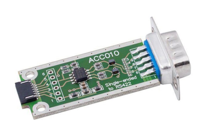
Source: DirectIndustry
TTL is the short form of transistor-transistor-logic and is known as the most balanced output for differential line outputs. The signal provided by TTL is called RS422. Even if the supply voltage is low or high, it would be +5VDC when you activate it. What that means is whatever the voltage supply is, you are only going to get 0 volts or 5 volts, if you are in a low voltage state or a high voltage state respectively. TTL is one of the best output signals as the signal from RS422 gives off signals that are extremely suppressed in noise, is blazing fast and quick, and can be used for lengthy cables. The supply voltage for TTL is 4.75-30 V in both, high and low states and its output voltage can range from 0-5 V.
2. HTL

Source: SlideShare
HTL is the short form of High Transistor Logic. It is a circuit that makes use of two transistors in the form of a dual polar totem configuration to generate output signals that are either in a high state or low state. The most interesting thing about HTL is that when the circuit is activated, the output voltage is the same as the supply voltage. When turned off, the output signal is transferred to the common line. A signal that exceeds 3 V is a high state and a signal that is lesser than 1 V is said to be a low state. Since there is such a huge difference in the voltage of the two states, HTL has immunity to interference and is also considerably more resistant to any electric noise. HTL logic is used when there is a signal receiving device that needs signals of either 12V or 24V, such as controllers.
3. NPN

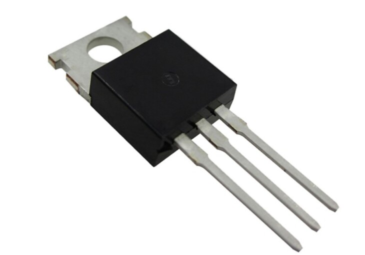
Source: Filotronix
Perhaps the simplest in our lot is the NPN logic gate. It’s very rudimentary in function as well as structure. It’s a basic sinking output. When the circuit is activated, the output signal is pulled low. When it’s not activated, the signal is at a floating level. Being an intuitive yet simple design, this circuit design can be used in applications with short cable lengths. NPN is the most vulnerable to noise from electricity than TTL or HTL. Therefore, NPN should be used in devices that are resistant to electrical noise and don’t require lengthy cables.
These outputs are created from each separate resolution and rotation of the shaft. Most times, incremental encoders are only limited to outputting one single specific type, which may not even be the one you want. However, there are encoder models that can be programmed to display whatever output type you like. The most exciting benefit from this is that these encoders are usable in multiple devices and equipment. These encoders also allow you to modify the pulses per signal which opens up a whole new world for customization.
Conclusion
As discussed, an incremental encoder can generate and output several types of output signals. Each of these signals is compatible with a certain device it needs to work properly. We hope that by reading this article you gain insight into the workings of an incremental encoder and its application in our everyday life. If this article helped you out, please follow our website for regular updates as it will help us out immensely.
